Categories
IoT

JSON on the Meadow MCU

From a thread I responded to on the Wilderness Labs forums, I got the Meadow microcontroller building a JSON object and sending the result to a .net API server

The question came from someone trying to use the NewtonSoft JSON framework which has too many associated libraries and the Meadow runs out of memory.

When I moved the code from NewtonSoft to System.JSON, it was interesting to watch how many DLLs were uninstalled from the Meadow:

[26/01/2021 20:39:02] Meadow successfully deleted 'Newtonsoft.Json.dll'
[26/01/2021 20:39:12] Meadow successfully deleted 'System.Xml.Linq.dll'
[26/01/2021 20:39:22] Meadow successfully deleted 'System.Runtime.Serialization.dll'
[26/01/2021 20:39:32] Meadow successfully deleted 'System.ServiceModel.Internals.dll'
[26/01/2021 20:39:42] Meadow successfully deleted 'System.Data.dll'
[26/01/2021 20:39:52] Meadow successfully deleted 'System.Transactions.dll'
[26/01/2021 20:40:02] Meadow successfully deleted 'System.EnterpriseServices.dll'

The other challenge was that (at the time of writing) the Meadow doesn’t support TLS and most publicly available API’s are https URLs. So I built a local API server to test against.

The class on the Meadow looked like this now

public async Task SendNotification()
{
Console.WriteLine("Start Notification: " );
try
{
string uri = "http://192.168.1.11:8002/api/MeadowLogs";
Console.WriteLine("Build object: ");
var data = new
{
LogData = "Meadow"
};
Console.WriteLine("Serialize Data: ");
string httpContent = JsonSerializer.Serialize(data);
Console.WriteLine(httpContent);
Console.WriteLine("Build httpcontent: ");
var stringContent = new StringContent(httpContent);
Console.WriteLine("Create http client: ");
var client = new HttpClient();
Console.WriteLine("Adding Headers: ");
stringContent.Headers.ContentType = new System.Net.Http.Headers.MediaTypeHeaderValue("application/json");
Console.WriteLine("Sending Message: ");
var response = await client.PostAsync(uri, stringContent).ConfigureAwait(false);
var result = response.Content.ReadAsStringAsync();
if (response.IsSuccessStatusCode)
{
return true;
}
else
{
Console.WriteLine(response.ReasonPhrase);
return false;
}
}
catch (TaskCanceledException ex)
{
Console.WriteLine(ex.ToString());
return false;
}
catch (Exception ex)
{
Console.WriteLine(ex.ToString());
return false;
}
}

The code for the Meadow, the API server and the sql for a backend Postgres database table are all up on github
https://github.com/unixbob/MeadowJSON

Categories
IoT projects

Raspberry PI TFT Screen / USB Bitcoin Miner

Earlier this year I built a Bitcoin mining project with my old Raspberry PI.  Even though it’s the older model, the USB ASIC offloads all of the CPU processing so it’s an ideal project for the older PI (there’s a whole separate thread around whether we really need the extra CPU horsepower in the newer PI’s.  Although a benefit is that the old model B’s will probably get a lot cheaper on ebay)

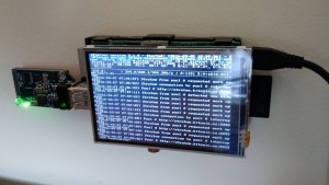
 IMG_20160307_085113090

Buyer Beware – I did this about 4 weeks ago and had loads of fiddling to make it work.  I’ve gone back through bash histories to document everything I did.  If I’ve missed anything then that’s my excuse.  But feel free to drop me a line if you’ve tried stuff and it doesn’t work.

I installed a clean version of Jessie to start the project.  But I had to do a fair amount of fiddling to get the screen up and running.   Most of the effort in getting this project working was around getting the screen to a) work, and b) stay on.  As such I thought I’d document it here to see if it helps anyone.

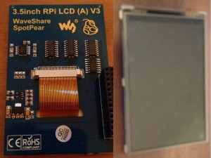
The screen I picked up is from Amazon – described as a “Makibes® 3.5 inch Touch Screen TFT LCD (A) 320*480 Designed for Raspberry Pi RPi/Raspberry Pi 2 Model B”.  The back of the screen says “3.5inch RPi LCD (A) V3 WaveShare SpotPear”.

screen

I think the Makibes thing is a rebrand as most of the google search results for the errors I was getting were brought up the WaveShare screen.  As per the comments in the Amazon page, this link many found helpful.  It got me to the point where I could manually load the modules.  But it didn’t stay persistent over the reboot.  As per the page I just linked to (and I’m just copying and pasting his work here, check out the link for the full info), I could get the screen working with a modprobe

modprobe flexfb nobacklight regwidth=16 init=-1,0xb0,0x0,-1,0x11,-2,250,-1,0x3A,0x55,-1,0xC2,0x44,-1,0xC5,0x00,0x00,0x00,0x00,-1,0xE0,0x0F,0x1F,0x1C,0x0C,0x0F,0x08,0x48,0x98,0x37,0x0A,0x13,0x04,0x11,0x0D,0x00,-1,0xE1,0x0F,0x32,0x2E,0x0B,0x0D,0x05,0x47,0x75,0x37,0x06,0x10,0x03,0x24,0x20,0x00,-1,0xE2,0x0F,0x32,0x2E,0x0B,0x0D,0x05,0x47,0x75,0x37,0x06,0x10,0x03,0x24,0x20,0x00,-1,0x36,0x28,-1,0x11,-1,0x29,-3 width=480 height=320
modprobe fbtft_device name=flexfb speed=16000000 gpios=reset:25,dc:24

If your screen matches the description above and that works, then happy days.  Here’s what I ended up doing to make it persistent post reboot:

First off, if it isn’t already enable SPI in the raspi-config tool

in  “/boot/config.txt” I’ve appended the following lines

Enable audio (loads snd_bcm2835)
dtparam=spi=on
# dtoverlay=ads7846,cs=1,penirq=17,penirq_pull=2,speed=1000000,keep_vref_on=1,swapxy=0,pmax=255,xohms=60,xmin=200,xmax=3900,ymin=200,ymax=3900
dtoverlay=ads7846,speed=500000,penirq=17,swapxy=1
dtparam=i2c_arm=on
dtoverlay=pcf2127-rtc
# dtoverlay=w1-gpio-pullup,gpiopin=4,extpullup=1
device_tree=on

/boot/cmdline.txt passes parameters to the bootloader.  I’ve appended a couple of lines to make the console appear on the SPI TFT screen instead of the default HDMI.  Also, the console blanking is disabled

dwc_otg.lpm_enable=0 console=ttyAMA0,115200 console=tty1 root=/dev/mmcblk0p2 rootfstype=ext4 elevator=deadline fsck.repair=yes rootwait fbcon=map:1 fbcon=font:ProFont6x11 logo.nologo consoleblank=0

/etc/modules now looks like this:

snd-bcm2835
i2c-bcm2708
i2c-dev

Something I didn’t pick up from other forum posts and blogs is the config required to auto load modules on bootup.  So I created /etc/modules-load.d/fbtft.conf to effectively do what modprobe is doing from the command line

spi_bcm2708
flexfb
fbtft_device

Console Blanking is apparently a bit busted in Jessie, so /etc/kbd/config needs the following settings (they aren’t next to each other in the file so you’ll need to search through it to make both edits:

BLANK_TIME=0
POWERDOWN_TIME=0

And /etc/init.d/kbd needs to look like this (search for screensaver stuff in the file – it’s quite long)

# screensaver stuff
setterm_args=""
if [ "$BLANK_TIME" ]; then
setterm_args="$setterm_args -blank $BLANK_TIME"
fi
if [ "$BLANK_DPMS" ]; then
setterm_args="$setterm_args -powersave $BLANK_DPMS"
fi
if [ "$POWERDOWN_TIME" ]; then
setterm_args="$setterm_args -powerdown $POWERDOWN_TIME"
fi
if [ "$setterm_args" ]; then
# setterm $setterm_args
TERM=linux setterm > /dev/tty1 $setterm_args
fi

That should get you to the point where your Raspberry PI will reboot and then always use the TFT screen as a display output.

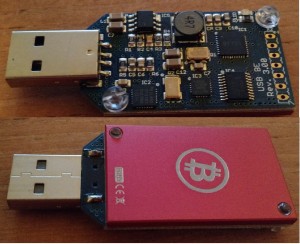
To complete the project I used this USB ASIC to do my bitcoin mining.  Amazon is out of stock at the time of writing.  However it will give you what you need to search ebay for, etc.  This instructables is complete enough that there’s little point me replicating it here.  However, there were a couple of additions that I needed to do before it worked and to complete the project.

dongle

First off I needed to install some additional packages:

sudo apt-get install autoconf autogen libtool uthash-dev libjansson-dev libcurl4-openssl-dev libusb-dev libncurses-dev git-core

Download the zip file, build and install the code

wget http://luke.dashjr.org/programs/bitcoin/files/bfgminer/3.1.4/bfgminer-3.1.4.zip
unzip bfgminer-3.1.4.zip
cd bfgminer-3.1.4
make clean
./autogen.sh
./configure
make
sudo make install

The last part of the project is a total hack as I ran out of steam with my enthusiasm.  It’s pretty insecure and absolutely not best practise, etc. etc.  But I got lazy, and it works.  I’m sure you can make something better given a few more brain cells.  First off, make sure the pi boots into console mode and not x windows.(option number 3 in raspi-config).  Then choose option

B2 Console Autologin Text console, automatically logged in as 'pi' user

Then I created  the following script – /home/pi/login.sh

#!/bin/bash
#
/usr/local/bfgminer-3.1.4/bfgminer -o stratum.bitcoin.cz:3333 -O username.password -S all

Every time it boots, the Raspberry PI automatically logs in as the ‘pi’ user.  And everytime the pi user logs in, that script is run.  Totally insecure.  And I’ll probably go back and fix it when I’ve got a spare 30 minutes.  But it works for now

Categories
IoT

Windows 10 IoT Install Guide

What you need to install Windows 10 IoT on the Raspberry Pi 2

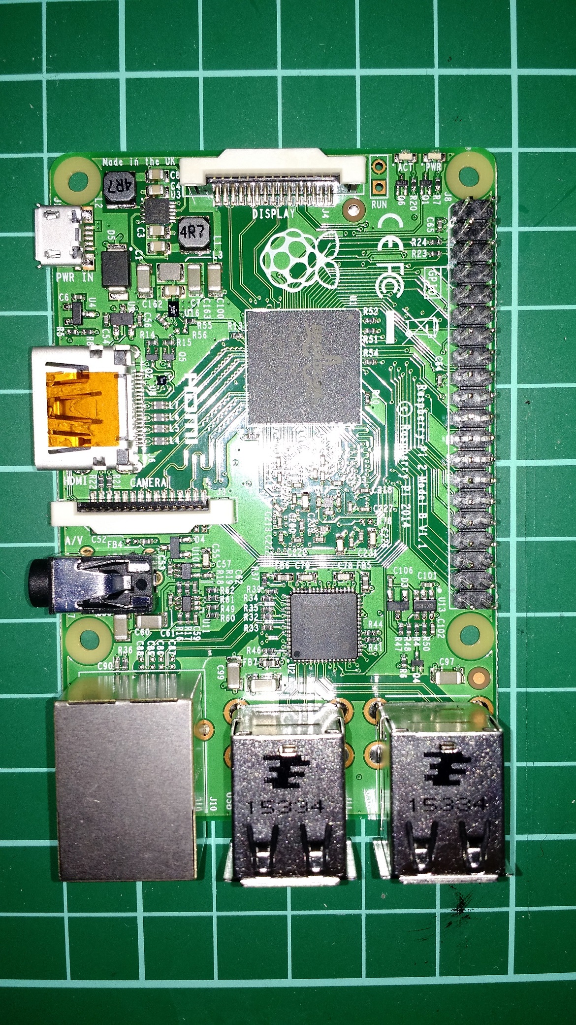
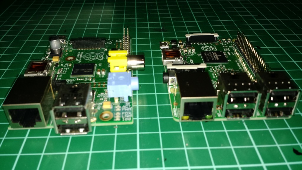
First thing to think about it to understand the Raspberry Pi 2 is different to the original Raspberry Pi

IMG_20160104_191018042


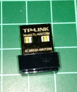
The form factor is different.  If you have a Raspberry Pi and are upgrading, you’ll want a different case.  Second point is that you are installing a different OS so you’ll need to consider whether your hardware is compatible.  For my Raspberry Pi running Raspian I use an old Buffalo WLI-UC-GN.  I just pulled this out of my spare parts bin when I setup Raspian.  In hindsight I probably purchased the Buffalo card because it was Linux compatible.  The Windows 10 IoT Hardware Compatibility list is here.  From that list I purchased this TP-LINK Wireless USB Adapter and it worked first time for me.

IMG_20160104_191416625

For the case I picked up this case and it has a couple of nice features:

IMG_20160104_191841083

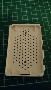
The base is full of holes which helps airflow.

IMG_20160104_192033606

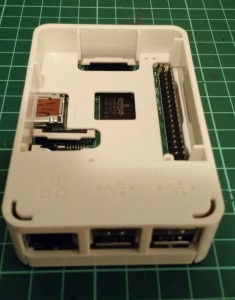
The case also has a middle layer so you can have most of the unit protected but also expose the the expansion ports.  That’s more by accident than design – I was just looking for a cheap case.  But I’m quite happy with what turned up so thought it was worth sharing.

Once you’ve got the hardware ready you’ll want to install the O/S.  For this you’ll need an Micro SD card and the Windows IoT Dashboard.  Go to Microsoft’s Get Started with Windows IoT and scroll down to the “Set up a Windows 10 IoT Core Device” section to download the software.

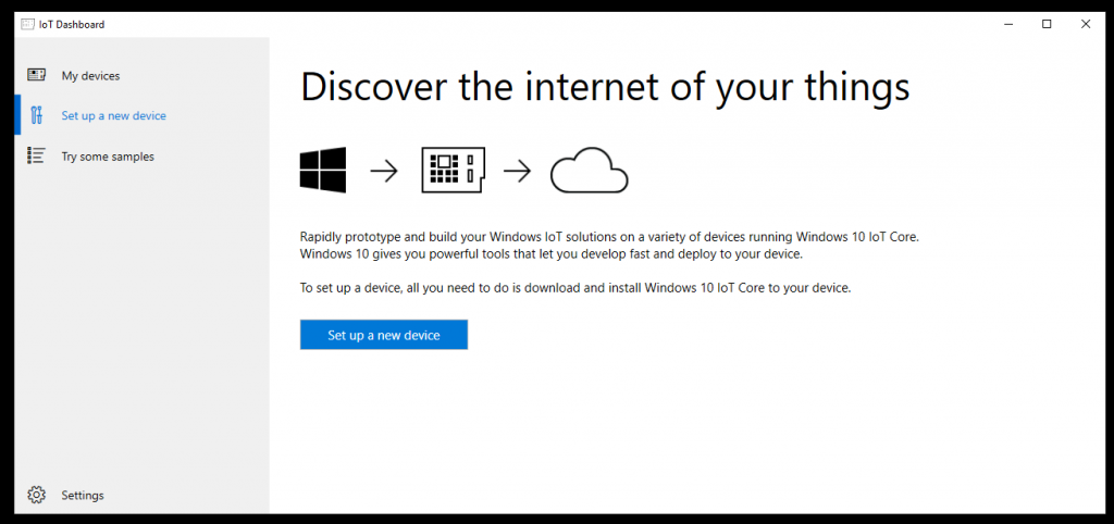
Fire up the software and the default page is the “Set up a new device”.

page 1

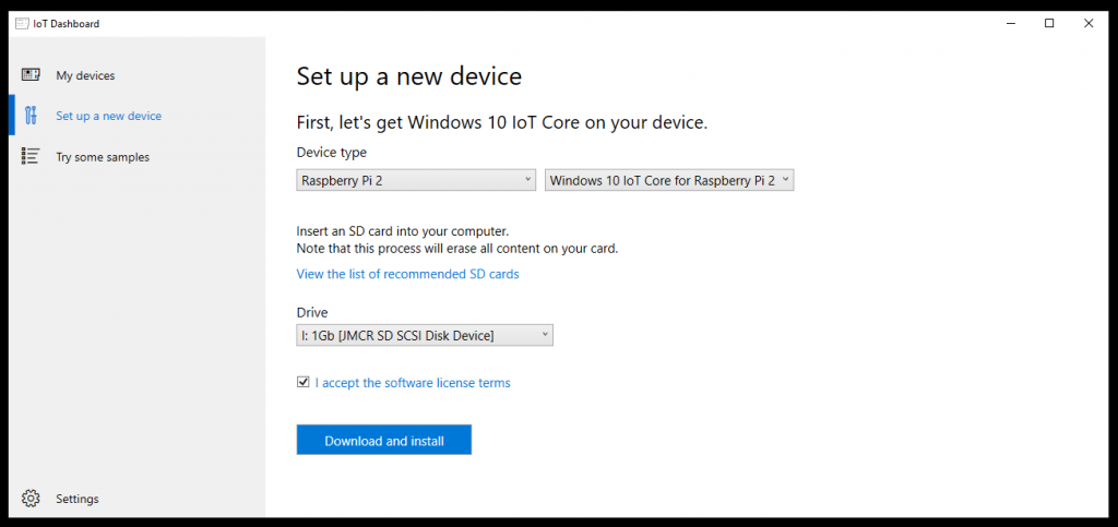
Insert an SD card and click the “set up a new device” button.

page 2

The tool will then download the software and burn the image to the Micro SD card.  Insert the Micro SD into the Raspberry PI and power it on.  You’ll want to be on the same Ethernet network as the Raspberry PI because you configure the device over the network.  The difference between the Windows 10 configuration and the Raspbian configuration is that I can plug a keyboard and mouse into the Linux setup and configure networking from there.  Windows assumes this is a device purely for Internet of Things so all configuration is done over the network from a PC.

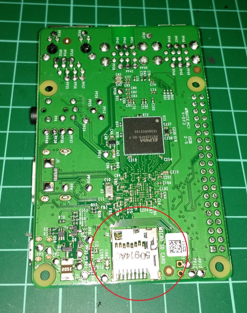
Note that the Micro SD card is underneath the PI 2, not on top like the first Model B.

IMG_20160104_191043464


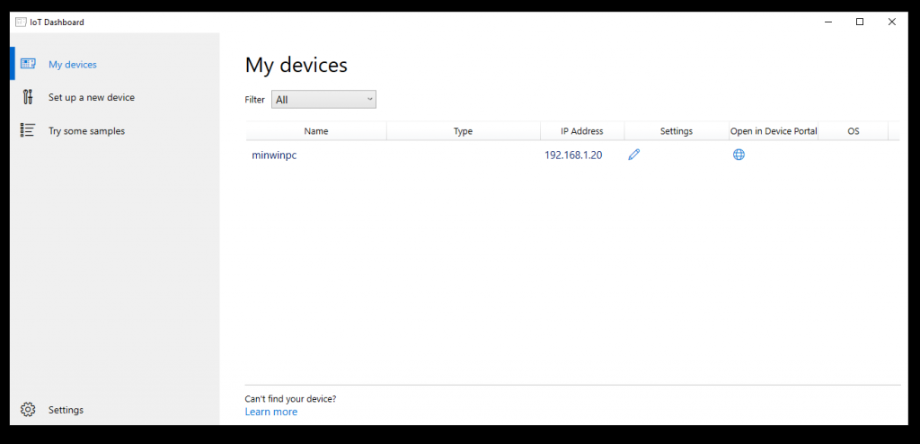
After a while you should see the minwinpc appear in the “My Devices” section of the IoT

page 3

Click on the Globe logo under “Open in Device Portal” and it will launch a web browser.  I’m only going off my own experience but whilst I generally like the Microsoft Edge Browser, it didn’t really like the Windows 10 IoT device configuration portal.  Silly things like the buttons didn’t seem to press when I was trying to get it to do things.  Chrome didn’t seem much better.  I had the best results with Internet Explorer 11.  YMMV

As you can see from the previous page, my Raspberry PI was DHCP’d the address 192.168.1.20.   Therefore the login page is http://192.168.1.20:8080/.

Default username is

Administrator

Default password is

p@ssw0rd

Note the ‘@’ and the zero instead of the letter ‘o’

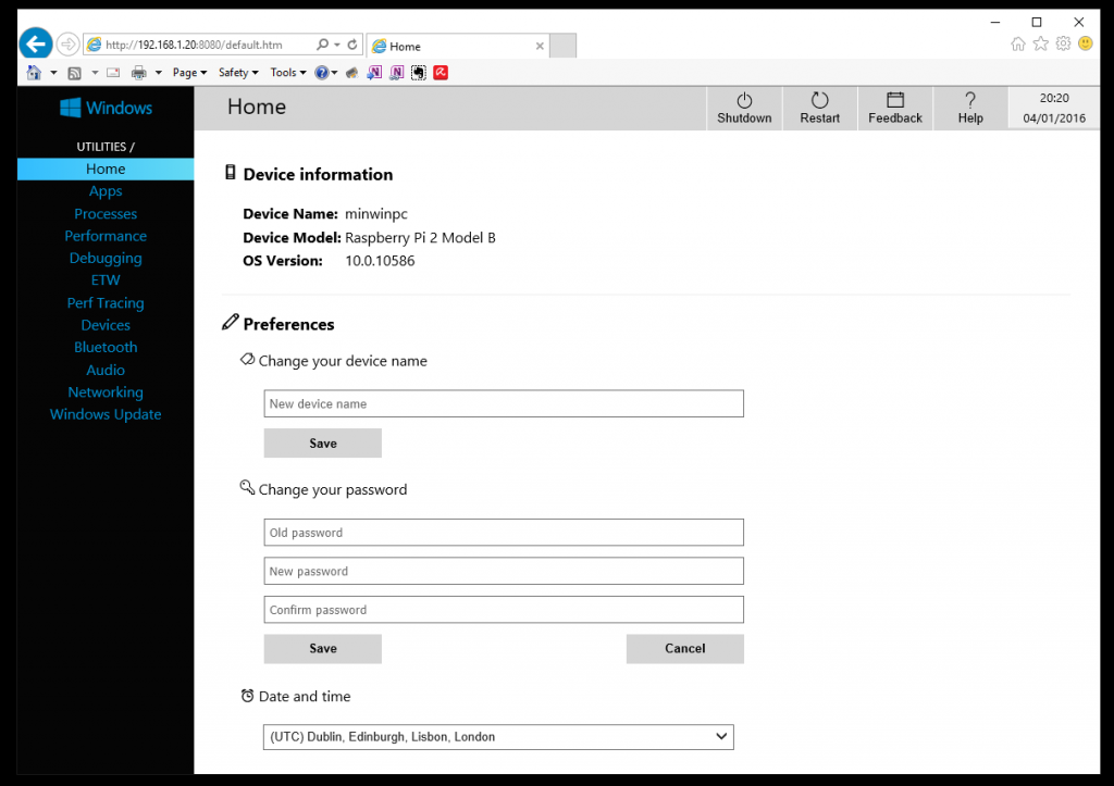
Now you can see the configuration web page where you can setup the Raspberry PI.  If you’re security conscious or running on a LAN with other users, then you should change the default password.  And probably change the name of the Raspberry PI from ‘minwinpc’ to uniquely identify your device. page 4

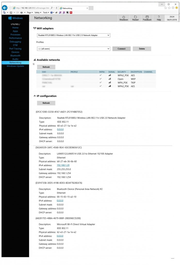
In the Networking page you can then configure the wireless settings:

page 5

Now you should have a Raspberry PI2 running Windows 10 IOT.  Enjoy

Categories
IoT projects

Raspberry PI RTC X100

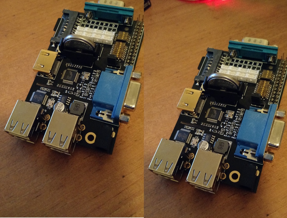
Here is how to get the Real Time Clock (RTC) for the X100 Raspberry PI expansion board working in Jessie.  Much of the information I found was out of date or for older versions of Raspbian.  To check out which version of the expansion board you have, there’s a decent write up on Sainsmart.  My X100 Board on my original Model B looks like this


X100 sidebyside


There are instructions on that SainSmart link for getting the different components of the expansion board up and running, including the real time clock.  However they’re horrendously out of date, including the suggestion to install version 3.0 of the Linux Kernel.  A bit of detective work shows that the rtc on the X100 expansion board is actually the RasClock.  (you can tell because the Sainsmart page has copied AfterThought’s instructions for setting up “Setting up on old version of Raspbian”

It wasn’t massively clear from their instructions what I needed to to do to get the clock working.  A bit fiddling got me the following steps:

1.  Check which overlay you have:

# ls/boot/overlays/

2. Follow the Afterthought Instructions (quoted here for convenience)

If you see the file /boot/overlays/i2c-rtc-overlay.dtb. To enable this add the following line to /boot/config.txt:

dtoverlay=i2c-rtc,pcf2127

If you see the file /boot/overlays/pcf2127-rtc-overlay.dtb. To enable this add the following line to /boot/config.txt:

dtoverlay=pcf2127-rtc

Edit the file /lib/udev/hwclock-set

  • Comment out or remove the three lines
if [ -e /run/systemd/system ] ; then
    exit 0
fi
  • Comment out or remove the two lines which contain --systz

 Now reboot your PI

3. Getting and Setting the time

The first time you use the clock you will need to set the time. To copy the system time into the clock module:

sudo hwclock -w

To read the time from the clock module:

sudo hwclock -r

To copy the time from the clock module to the system:

sudo hwclock -s

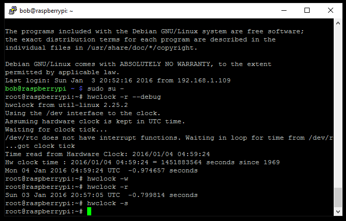
On my system, it looked like this:

hwclock

I did also enable the I2C and SPI bus’s on the PI during this process.  I don’t think that actually affected the RTC but maybe something to have a look at if yours isn’t working.